TIEPolylineLayer.AddPoint
Declaration
procedure AddPoint(X, Y: integer; PointBase: TIEPointBase = iepbRange; SnapAngles: Boolean = False); overload;procedure AddPoint(pt: TPoint; PointBase: TIEPointBase = iepbRange; SnapAngles: Boolean = False); overload;
// Complex path overload
procedure AddPoint(X, Y: integer; PointBase: TIEPointBase; Action: TIEPathAction; ClosePath: Boolean = False;
CurveX1: Double = 0; CurveY1: Double = 0; CurveX2: Double = 0; CurveY2: Double = 0;
ArcLarge: Boolean = False; ArcSweepCW: Boolean = False); overload;
Description
Add a point to the end of a polyline.Each point of the polyline is represented by an x and y value in the range 0 to 1000. Where (0, 0) is the top-left pixel of the layer and (1000, 1000) is the bottom-right. Values less than 0 or more than 1000 will increase the size of the layer.
There is also a complex path overload that allows you to add curves and arcs.
| Parameter | Description |
|---|---|
| X, Y | The point to add |
| PointBase | What base units point values are specified in |
| SnapAngles | Set to true to adjust the angle to ensure it aligns with LayersRotateStep (e.g. force it to 45 deg. steps) |
Note: You specify point($FFFFF, $FFFFF) to insert a break in the array (to create multiple polylines/polygons), or point($FFFEE, $FFFEE) if the break should close the polyline (to create a polygon)
Complex Path Notes:
◼For an iepaBezierCurveTo you must set: CurveX1, CurveY1, CurveX2, CurveY2
◼For an iepaQuadraticCurveTo you must set: CurveX1, CurveY1
◼For an iepaArcTo you must set: CurveX1 (= ArcRadiusX), CurveY1 (= ArcRadiusY), CurveX2 (= ArcRotation), ArcLarge, ArcSweepCW
Examples
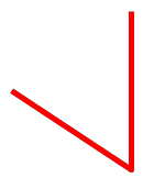
// Draw a polylineWith TIEPolylineLayer( ImageEnView1.CurrentLayer ) do
begin
ClearAllPoints();
AddPoint( 500, 0 );
AddPoint( 1000, 1000 );
AddPoint( 0, 1000 );
end;
ImageEnView1.Update();

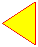
// Draw a triangle polygon
With TIEPolylineLayer( ImageEnView1.CurrentLayer ) do
begin
ClearAllPoints();
AddPoint( 500, 0 );
AddPoint( 1000, 1000 );
AddPoint( 0, 1000 );
PolylineClosed := True;
end;
ImageEnView1.Update();

// Draw a fat blue N
ImageEnView1.LayersAdd( ielkPolyline, 100, 100, 200, 400 );
With TIEPolylineLayer( ImageEnView1.CurrentLayer ) do
begin
AddPoint( 0, 1000 );
AddPoint( 0, 0 );
AddPoint( 1000, 1000 );
AddPoint( 1000, 0 );
LineWidth := 20;
LineColor := clBlue;
PolylineClosed := False;
end;
ImageEnView1.Update();
// Add a point that will double the width of the layer
TIEPolylineLayer( ImageEnView1.CurrentLayer ).AddPoint( 130, 2000 );
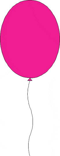
// Draw a pink balloon
ImageEnView1.LayersAdd( ielkPolyline, 100, 100, 600, 800 );
With TIEPolylineLayer( ImageEnView1.CurrentLayer ) do
begin
AddPoint( 500, 500 );
AddCurvePoints( 0.95, Point( 500, 0 ));
AddCurvePoints( 0.95, Point( 500, 500 ));
AddPoint($FFFEE, $FFFEE); // End shape and close polyline
AddPoint( 500, 500 );
AddPoint( 520, 517 );
AddPoint( 480, 517 );
AddPoint($FFFEE, $FFFEE); // End shape and close polyline
AddPoint( 500, 517 );
AddCurvePoints( 3, Point( 500, 690 ));
AddCurvePoints( -3, Point( 510, 850 ));
AddCurvePoints( 3, Point( 500, 1000 ));
AddPoint($FFFFF, $FFFFF); // End polyline (optional at end)
LineWidth := 2;
FillColor := $00921CF0;
PolylineClosed := False;
end;
ImageEnView1.Update();

// Create a polyline layer with a complex path
ImageEnView1.LayersAdd( ielkPolyline );
polyLayer := TIEPolylineLayer( ImageEnView1.CurrentLayer );
polyLayer.BorderColor := clWebOrange;
polyLayer.BorderWidth := 30;
polyLayer.FillColor := clNone;
polyLayer.PolylineClosed := False;
polyLayer.AddPoint( 10, 10, iepbBitmap, iepaMoveTo );
polyLayer.AddPoint( 90, 10, iepbBitmap, iepaLineTo );
polyLayer.AddPoint( 50, 10, iepbBitmap, iepaMoveTo );
polyLayer.AddPoint( 50, 190, iepbBitmap, iepaLineTo );
polyLayer.AddPoint( 10, 190, iepbBitmap, iepaMoveTo );
polyLayer.AddPoint( 90, 190, iepbBitmap, iepaLineTo );
ImageEnView1.Update();

// Create a curved polyline layer with a complex path
ImageEnView1.LayersAdd( ielkPolyline );
polyLayer := TIEPolylineLayer( ImageEnView1.CurrentLayer );
polyLayer.BorderColor := clGreen;
polyLayer.BorderWidth := 3;
polyLayer.FillColor := clYellow;
SetLength( pts, 3 );
SetLength( fmts, 3 );
// M 70,30
fmts[0].Action := iepaMoveTo;
pts[0] := DPoint( 70, 30 );
// C 130,-30 130,90 70,30
fmts[1].Action := iepaBezierCurveTo;
fmts[1].CurveX1 := 130;
fmts[1].CurveY1 := -30;
fmts[1].CurveX2 := 130;
fmts[1].CurveY2 := 90;
pts[1] := DPoint( 70, 30 );
// C 10,90 10,-30 70,30 Z
fmts[2].Action := iepaBezierCurveTo;
fmts[2].CurveX1 := 10;
fmts[2].CurveY1 := 90;
fmts[2].CurveX2 := 10;
fmts[2].CurveY2 := -30;
pts[2] := DPoint( 70, 30 );
fmts[2].ClosePath := True;
polyLayer.SetPoints( pts, fmts, iepbBitmap );
ImageEnView1.Update();

// Add the following SVG Arc path: <path fill="#0c64d2" d="M49 58 A42 42 10 1 0 50 58z"/>
TIEPolylineLayer( ImageEnView1.CurrentLayer ).AddPoint( 49, 58, iepbBitmap, iepaMoveTo );
TIEPolylineLayer( ImageEnView1.CurrentLayer ).AddPoint( 50 58, iepbBitmap, iepaArcTo, True, 42, 42, 10, True, False );
ImageEnView1.Update();
See Also
◼InsertPoint◼RemovePoint
◼SetPoint
◼SetPoints
◼Points